Standalone LinuxCNC console - 2/2

Creation of a fully autonomous CNC control console (no need for a computer) with an architecture based on the use of a Beaglebone Black board configured with MachineKit (Embedded LinuxCNC), this console allows you to control up to 5 axes and is equipped with a touch screen allowing access to all functions of LinuxCNC. The Beaglebone has many inputs / outputs which allows to have the necessary functions for most hobbyits machining machines. 

This second part describes the console itself, its realization and especially the setting of LinuxCNC (MachineKit). 
For memory, the first part talk about the specifications to the realization of the interface board to plug on the Beaglebone Black.

Realization and wiring of the cabinet

Overview

This cabinet console is designed to provide all the main functions to control different types of machines up to 5 axes. 
Only machine-specific functions are not directly integrated, but in this case the input/output lines are transferred to the sub D connectors on the side panel. Thus this console allows to have a set that can be modulated but also easily transportable from one machine to another, even if for now I have only one machine. 
The idea of ​​this project came to me by reading the F1oat blog which among many other topics presents the retrofit of an EMCO lathe
This console provides next features :

- Beaglebone Black and BBB-CNC-Cape. 
- 12 inch touch screen. 
- USB hub with 4 outputs. 
- 5V / 12V power supply 
- 5 axis drivers (4 currently mounted). 
- Toroidal transformer for the axis power. 
- Filtering rectifier for the axis power. 
- 3 fans. 
- Emergency stop. 
- 2 override potentiometers. 
- 2 status lights. 
- Safety switch 220V power on/off. 
- 2 protection circuit breakers. 
- 3 USB connectors (2 on the front). 
- 1 RJ45 connector. 
- 5 sub D 9 pins for the axes. 
- 1 sub D 9 pins for the spindle. 
- 1 sub D 25 pins for inputs/outputs.
With this configuration, the console has everything you need to operate the 5 axes and the axis output connectors allow you to directly plug the stepper motors. 
 
The choice of not integrating machine-specific functions means that the spindle drive and the drive controller are not in the cabinet, so a data wiring must be provided between the cabinet and the machine in order to send the signals required on the spindle (on/off, PWM, CW/CCW, encoder), and the same for all auxiliary functions. 
 
The global layout is described by the following diagram.

The realization

The cabinet is made of a structure from Alfer aluminum square pipes assembled by plastic nodes from the same supplier. This assembly is sucured with pop rivets and crimped nuts for the removable panels. 
The top and the bottom are closed by aluminum sheet thickness 1.5mm fixed to the structure by pop rivets, the upper handle is screwed on the structure, it allows to easily move the cabinet. 
The front, rear and side panels can be dismounted to access all the elements.
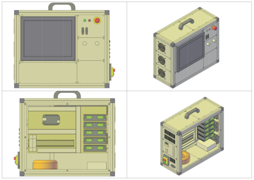
On the front side there is of course the 12 inch touch screen and to its right a first panel with the emergency stop, the status lights and two USB connectors, one of them is used for the keyboard and mouse dongle. 
Below, a second panel carries feedrate and spindle override potentiometers. 
Later, when everything will work, the panels will be engraved with the various indications of functions. 
The bottom will be closed by other sheet metal panels when everything is finished. 
 
The 4 motors fixed on the left side are only for the development phase, they allow to visualize the operation without being connected to the machine.
We can access all the equipment installed from the back side. 
Top left Beaglebone and cape BBB-CNC-Cape. 
On the right the stepper drivers. 
In the lower part the power supplies. 
The side panel on the drivers side carries the three fans working in extraction to cool everything, the air flow enters through grids on the opposite side and cooled the equipment starting with the least hot elements to finish the drivers. 
The opposite panel to the drivers will carry the main switch and the various input/output connectors, the upper part of this panel will only be composed of an air intake grille. 
For ventilation to work properly, the back panel must be closed.
The previous picture shows the Beaglebone Black with the BBB-CNC-Cape plugged in. 
 
The HDMI and USB cables go respectively to the screen and to the USB hub (which will distribute to the connectors and the screen). 
 
The micro SD card must remain accessible to perform the various updates. 
 
When the picture was taken, the wiring was in progress, which is why the motor control lines are not yet in place. 
 
The mass and the voltages 5V and 12V are centralized on the two small connection blocks.
Looking through the other side, we can see the power supplies at the bottom, under the drivers a switching mode power supply that gives 12V (screen and fans) and 5V (Beaglebone and electronics). The power of the motors is provided by a toroidal transformer followed by a rectifying and filtering module equipped with four bridges (one for each motor) for a better distribution of the load. The CNC Loisirs website gives all the information on calculating your power supply. 
 
Most wires leads through small wiring ducts  for a cleaner result.
As you can see in this article, the LinuxCNC console is far from over, there is still a lot of wiring and testing to do. 
But later the setup part will also be very long in development because LinuxCNC and MachineKit allow almost everything to configure as it is possible to do it on an industrial installation. 
See more
F1oat blog
The blog that gave me the idea to make this console. The author of the blog has rebuilt a lathe by creating a cabinet with a Beaglebone and a touch screen.
Forum usinage
This french forum talks about everything related to hobby or professional machining. Some threads about LinuxCNC on the Beaglebone, the one given in this link was also one of my starting points.
CNC Loisirs
French site on the hobbyist CNC home made, you will find everything you need to design and build a machine.
Suppliers
Beetonics
The site where I bought the 12 inch touch screen.
Alfer
Aluminum profiles and accessories available in most DIY superstores.
See more
Blog F1oat
The blog that gave me the idea of ​​this project
Forum usinage
Thread on LinuxCNC and Beaglebone
Suppliers
Beetronics
12 inch touch screen
Alfer
Aluminum profiles in DIY stores

The fully fonctionnal console

The console is finally fully functional with all the connections, the touch screen, the management of the potentiometers, the control of a brushless milling spindle (ER11), the control of the plugs to operate the lathe spindle and the coolant system.
And thanks to the functionalities of LinuxCNC I can finally make threads with the lathe and this "simply" by adding a homemade encoder on the spindle in order to synchronize the feedrate.

You can download my configurations as well as an image of the SD card containing all the Linux environment and Machinekit installed, plug and play, be careful because the image weighs just under 500MB.
The inside of the console with the Beaglebone Black and the BBB-CNC-Cape version 1.

Below, next to the circuit breakers is a PWM to 0-10V converter for driving the spindle. The two relays are used to manage the start-up of the power only when Linux CNC has activated the machine, it is a question of safety at power-up.

A maximum of the wiring is under trunking for aesthetics.
The front of the console with of course the touch screen, I chose GmocCapy as the interface.

On the right the status lights and the emergency stop.

Two USB connectors to connect a key for the upload of machining programs.

The two potentiometers allow rapid action on the feedrate and the spindle speed, as on industrial CNCs.
On the right side, we find the main switch and the 220V plug.

The five connectors for powering the stepper motors are simple SubD 9.

A SubD 25 allows the different inputs/outputs to be connect.
The last SubD 9 is for spindle connection.

A USB socket and an RJ45 complete the possibilities of external connections.

The drilled grids are air inlets for ventilation, the extraction is ensured by three fans located on the left side.
For milling soft metals, a small brushless spindle with ER11 collet is perfect for my small machines.

As there is not enough space in the console to integrate the power supply and the driver, I built a remote box to place the essential components for the spindle.

This box is plugged to the console using the SubD 9 "SPINDLE" connector.
The inside of the brushless spindle control box.

With the power supply at the back, the driver in the middle with its cooling fan.

The two relays to control the on/off and the 220V socket.

In addition, on the back of the box a 220V socket controlled by one of the relays for coolant control.
LinuxCNC integrates the possibility of synchronizing feeds with the rotation of a non-servo lathe spindle, this allows threading.

To synchronize the feeds, a simple encoder must be placed on the lathe spindle. I made mine with optical forks and encoder wheel... milled with the small spindle.
This standalone LinuxCNC console allowed me to rediscover my little machine which was previously controlled with Cnc3Axes, the possibilities of LinuxCNC are incredible and finally relatively simple to integrate.
Thanks to this new equipment I now have a fully operational small machine.

I remain at your disposal for any questions about this project, for this you can use the contact form.

The success of this project even made me want to build a new, larger capacity CNC milling machine, but that's another story...
See more
Configs
All my configs for lathe and milling machine.
Machinekit image
The Machinkit image of all my system, just download and flash your SD card.
Download
Configs
My configs for lathe and mill
Machinekit image
My fully fonctionnal Machinekit image
Made with OpenElement
Date mise à jour  
CARNETS JL-S
Technical hobbies
Carnets JLS
Top page